
Installation Manual for the
SHURflo 902-200
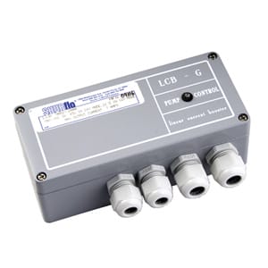
LCB - G Pump Controller
The "LCB - G" pump controller is a high quality DC power converter
designed as an interface between a DC (Solar)-Pump (e.g. SHURflo
9300) and a DC power source, like solar panels, wind generators,
batteries etc.. The main function of this controller is to maximize the
daily water output while providing protection for the pump. The
controller can be used in 12V and 24V systems.
The solid state controller will protect the pump system and give
trouble free service for many years. When used in a solar pumping
system, directly connected to the solar power, it will protect the pump
from over voltage and over current conditions as well as will provide
current boosting in low sunshine (radiation) conditions.
The manual will show you how to make the connection for your
particular system configuration and the wiring diagram is given.
INDUSTRIAL PRODUCTS LIMITED WARRANTY
SHURflo Industrial series pumps and products are warranted to be free of defects in material and workmanship under
normal use, for a period of one (1) year from the date of manufacture, or one (1) year of use, with proof of purchase. This
limited warranty will not exceed two (2) years, in any event.
The limited warranty will not apply to pumps/products that were improperly installed, misapplied, damaged, altered,
incompatible with fluids or components not manufactured by SHURflo.
All Industrial pumps/products must be flush of any chemicals before shipping*. All warranty considerations are governed
by SHURflo's written Return Policy.
Returns are to be shipped postage prepaid to either service center; SHURflo Garden Grove, CA or Elkhart, IN. SHURflo shall
not be liable for freight damage incurred during shipping. Package returns carefully.
SHURflo's obligation under this warranty policy is limited to the repair or replacement of the pump/ product. All returns
will be tested per SHURflo factory criteria. Products found not defective (under the terms of this limited warranty) are
subject to charges paid by the returnee for the testing and packaging of "tested good" non-warranty returns.
No credit or labor allowances will be given for pumps or products returned as defective. Warranty replacements will be
shipped on a freight allowed basis. SHURflo reserves the right to choose the method of transportation.
This limited warranty is in lieu of all other warranties, expressed or implied, and no other person is authorized to give any other
warranty or assume obligation or liability on SHURflo's behalf. SHURflo shall not be liable for any labor, damage or other
expense, nor shall SHURflo be liable for any indirect, incidental or consequential damages of any kind incurred by the reason
of the use or sale of any defective product or part. This limited warranty covers industrial products distributed within the United
States of America. Other world market areas should consult with the actual distributor for any deviation from this document.
RETURN POLICY
All industrial pumps/products must be flushed of any chemical (ref. OSHA Section 1910.1200(d)(e)(f)(g)(h) ) and hazardous
chemicals must be labeled / tagged before being shipped* to SHURflo for service or warranty consideration. SHURflo reserves
the right to request a Material Safety Data Sheet from the returnee for any pump/product it deems necessary. SHURflo
reserves the right to "disposition as scrap" pumps/products returned which contain unknown fluids. SHURflo reserves the right
to charge the returnee for any and all costs incurred for chemical testing, and proper disposal of components containing
unknown fluids.
SHURflo request this in order to protect the environment and personnel from the hazards of handling unknown fluids. *
Carriers, including U.S.P.S., airlines, UPS, ground freight, etc., require specific identification of any hazardous materials to be
shipped. Failure to do so may result in a substantial fine and/or prison term. Check with your shipping company for specific
instructions.
«ISO Certified Facility
SHURflo reserves the right to update specifications, prices, or make substitutions.
SHURflo ««
12650 Westminster Ave.
Santa Ana, CA 92706-2100
(800) 854-3218 (562) 795-5200
FAX (562) 795-7554
Shipping/UPS: 5900 Katella Avenue,
Suite B, C, Cypress ,CA 90630
SHURflo East
52748 Park Six Court
Elkhart, IN 46514-5427
((800) 762-8094
(219) 262-478
FAX (219) 264-2169
© 1999 Printed in USA
SHURflo Ltd.
Unit 5 Sterling Park
Gatwick Road, Crawley
West Sussex, RH10 2QT
United Kingdom
+44 1293 424000
FAX +44 1293 421880
911-193 Rev. C 1/98
a WICOR Company
Ò
= Page 1 =
LCB - G Specification
* Maximum input voltage 45 VDC (Open Circuit) under all
conditions
* Start up voltage with 12.5 V
one module 17,5 mpp
* Start up voltage with 25.0 V
two modules 17,5 mpp in series
* Maximum output voltage 29 volts
* Maximum power consumption 150 Watts
of the PV-pump-system
* Maximum output current 7 Amps
* Power consumption 25 mA
* Fuse 10 Amps (optional inserted on
the battery cable)
* Ambiente temperature 14°F - 113°F ( -10°C...+45°C )
* Short-circuit protection
Features
1) Current boosting for matching the load requirements of the pump
motor.
2) Adjustable voltage of the starting point of the pump.
3) Weatherproof cast aluminum enclosure.
4) 4x water tight cable inlets
5) Voltage limiting for pump protection
6) Remote float switch circuit.
7) Low water cut off circuit with adjustable set points.
8) ON / OFF Pump switch (inside enclosure)
9) Power-in indicator (green LED, inside enclosure)
("ON", if the wiring from the panel is correct)
10) Pump-out indicator (red LED, outside)
11) One year limited warranty
Power Matching of the Controller
For use on panel direct systems, the LCB Pump Controller is set to
hold the voltage constant around the maximum power point of the
panels, and match the electric requirements of the pump motor. The
purpose for the matching of the electric conditions of the power source
(MPP) with the consumer (load) is to maximize the daily output of the
solar pumping system.
= Page 2 =
Wiring the LCB Pump Controller
a. Float switch (remote) ON/OFF Circuit is used to turn the
pump on and off from a remote location, e.g. a float switch in a
reservoir. (Short the two terminals to turn the pump off.) The
resistant on the wire should not exceed 250 ohms.
b. HIGH water level sensor turns the pump on. ( * Mount the
brass electrode below the static water level at the desired turn
point.)
c. LOW water level sensor turns the pump off. (Mount the brass
electrode 1 foot above the ground sensor.
d. GROUND or common water level sensor must be under water
all times. Mount the electrode 1 foot (30cm) above the pump.
* The distance between the HIGH and GROUND sensor should
not exceed 60cm
(2 feet). It depends on the water conductivity
If more distance is required a test will give best results
e. PV- (IN) Negative wire from the PV array.
f. PV+ (IN) Positive wire from the PV array.
g. PUMP- (OUT) Negative wire from the pump (load).
h. PUMP+ (OUT) Positive wire from the pump (load).
i. ON/OFF Switch MANUAL SWITCH turns the pump on / off.
k. 12V/24V Switch select system voltage.
( presentadjustment:25V )
Switch no. 1 2 3 4
25 V
solar direct
two modules in
series "direct"
ON OFF OFF OFF
22 V
battery based
two batteries in
series
OFF ON OFF OFF
12.5V
solar direct
one module
"direct"
OFF OFF ON OFF
11 V one battery OFF OFF OFF ON
* Note:
If the low water level circuit (HI/LOW/GRD) is not used,
jumper wires must be connected all three terminals.
Do not extend sensor wires more than 300 feet (100 m) total
length
IMPORTANT = Watch for the correct electric connection =
IMPORTANT
("+" / "-" cable connection)
DO NOT EXPOSE THE CONTROLLER INTO
DIRECT SUNLIGHT
= Page 3 =
Function of the LED
* Green Light: The green LED is inside of the controller. If the
wiring from the panel correct, the green light
(LED) will be on.
* Red Light: The red LED is on the front side of the
controller. The red light is on:
a. If the float switch (remote control) is on a
high position and the reservoir is full (bridged).
b. If the water table inside the well is lowered to
the level of the LOW sensor and the dry
running protection of the pump is in function.
Battery Use
If the LCB Pump Controller is used in conjunction with batteries and
charge regulators, there must be a 10 A fuse on the cable to the
battery.
* IMPORTANT: Check for the correct cable ("+" /"-")
connection!!
Installation
1) If installing on a post, you may use the included Bracket and
screws.
2) Connect the PV-panel cable, while covering the solar modules
against sunshine (radiation). Correct connection will be
indicated by the GREEN LED.
3) Attach the HI/LOW/GRD sensors at the desired depth with the
pressure pipe of the solar pump and the safety rod.
4) Connect the solar pump cable. Tighten carefully!
5) Test the function by switching the manual switch (inside
enclosure, upper right corner) to the "ON" position some
seconds.
6) Connect the sensor cable while using the black isolation tube.
Insert all 3 wires through the isolation cable and then insert
through the cable connector. Tighten carefully!! Follow the
sequence of the sensor settings,
HIGH-sensor to the HIGH-cable connector, etc.
IMPORTANT:
If the HI/LOW/GRD terminals are not used with level
sensors they must be bridged. The RED LED is in
function when there is a low water level.
7) If required, connect the float switch with the terminals.
"Bridged", Stops the pump "RED LED".