
GRUNDFOS PRODUCT GUIDE
SQFlex
Renewable-energy based
water supply systems
50/60 Hz
= Page 1 =
Table of contents
2
SQFlex
1. Product data 3
Introduction 3
Applications 5
Features and benefits 5
Performance range 7
System overview 8
Identification 9
2. Construction 10
Material specification,
helical rotor pump 10
Material specification,
centrifugal pump 11
Material specification,
motor 12
3. Selection 13
Sizing of SQFlex system 13
Application examples 14
4. Solar panel wiring 23
Methods of solar panel wiring 23
5. Performance curves 25
Curve conditions 25
Curve charts 26
6. Technical data 32
Dimensions and weights 32
SQF pump 33
Motor 33
CU 200 SQFlex control unit 34
IO 50 SQFlex switch box 34
IO 101 SQFlex switch box 34
IO 102 SQFlex breaker box 34
Charge controller 34
7. Accessories 35
CU 200 SQFlex control unit 35
IO 50 SQFlex switch box 37
IO 101 SQFlex switch box 37
IO 102 SQFlex breaker box 37
Charge controller 38
Submersible drop cables 38
Whisper 200 wind turbine 39
GF100 solar panel 41
8. Further product documentation 42
WebCAPS 42
WinCAPS 43
= Page 2 =
Product data
SQFlex 1
3
1. Product data
Introduction
The SQFlex system is a reliable water supply system
based on renewable energy sources, such as solar
and wind energy. The SQFlex system incorporates an
SQF submersible pump.
Very flexible as to its energy supply and performance,
the SQFlex system can be combined and adapted to
any need according to the conditions on the installation
site.
The system components are
• SQF submersible pump
• CU 200 SQFlex control unit
• IO 50 SQFlex switch box
• IO 101 SQFlex switch box
• IO 102 SQFlex breaker box
• charge controller
• energy supply:
– solar panels
– wind turbine
– generator
– batteries.
SQF submersible pump
The SQF pump range comprises two pump
technologies:
• the helical rotor pump (3") for high heads and small
flows.
• the centrifugal pump (4") for low heads and large
flows.
The performance curves in fig. 1 illustrates the pump
performance for the two pump models.
Fig. 1 Performance ranges for helical rotor and
centrifugal pumps
The SQF pump is available as a complete unit only.
The SQF pump complete comprises:
• motor
• 6 ft (1.8 m) cable with water level electrode and
socket
• cable guard.
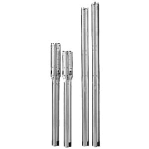
Fig. 2 SQF pump
Currently the complete range consists of six centrifugal
pumps and five helical rotor pumps. The centrifugal
pumps are adapted from Grundfos’ present 4” SP
range (16S, 25S, 40S, and 60S). These pumps are
used when lower heads and higher flow rates are
required.
The positive displacement helical pump ends are
3” in diameter and available in five models ranging
from 3 to 11 gpm (0.68 to 2.50 m 3/h). These are
designed for higher head and lower flow requirements.
The pump rotor is a single-twisted helix (spiral) made
of hard-chromium plated stainless steel. During
operation, the rotor rotates eccentrically in a double
helical elastic stator.
TM02 2425 3901 Q
H
A
B
A: Helical rotor pump
B: Centrifugal pump
/day
TM02 2217 3901
Pump type Pump size Product number
3 SQF 2 3" 95027332
3 SQF 3 3" 95027333
6 SQF 2 3" 95027334
6 SFQ 3 3” 96834840
11 SQF 2 3" 95027335
16 SQF 10 4" 95027350
25 SQF 3 4" 95027351
25 SQF 7 4" 95027353
40 SQF 3 4" 95027354
40 SQF 5 4" 95027355
60 SQF 3 4" 95027443
= Page 3 =
Product data
SQFlex 1
4
Motor
The motor has been developed specifically for the
SQFlex system and is de signed according to the
permanent-magnet principle with built-in electronic unit
and is available in only two sizes.
The motor speed range is 500-3600 rpm, depending
on power input and load.
The motor is constructed in 304 stainless steel.
Max. ratings are as follows:
• Maximum power input (P 1) of 1400 W
• maximum current of 8.4 A
• maximum speed of 3600 rpm
The pump delivers its maximum performance when
one of the above parameters is reached.
Fig. 3 Wiring diagram
The motor is to be connected to the power supply as
shown in fig. 3.
As the integrated electronic unit enables the motor to
handle both DC and AC supply voltages, it makes no
difference how the wires "+" and "–" or "N" and "L" are
connected.
Supply voltage
Flexible as regards power supply and power range, the
motor can be supplied with either DC or AC voltage:
• 30-300 VDC, PE
• 1 x 90-240 V –10 % / +6 %, 50/60 Hz, PE.
CU 200 SQFlex control unit
The CU 200 is a combined status and control unit for
the SQFlex pump system. Moreover, the CU 200
enables connection of a level switch placed in a water
reservoir or tank.
IO 50 SQFlex switch box
The IO 50 is an on/off switch box designed for opening
and closing the system power supply.
IO 101 SQFlex switch box
The IO 101 is an on/off switch box designed for
opening and closing the syst em power supply and is
used in solar-powered SQFl ex systems with a back-up
generator.
IO 102 SQFlex breaker box
The IO 102 is an on/off breaker box designed for
opening and closing the syst em power supply and is
used in wind-powered SQFlex systems or wind- and
solar-powered SQFlex systems.
The IO 102 makes it possible to slow down or stop the
wind turbine.
Charge controller
The charge controller is used when a battery backup
system is installed with an SQFlex pumping system.
Solar modules
Grundfos’ solar modules have been developed
specifically for the SQFlex system. The solar modules
are equipped with plugs and sockets enabling easy
connection in series or parallel.
For further information on solar modules, please
contact your local Grundfos company.
Generator
In case the power supply from its primary source of
energy is temporarily insufficient or unavailable, the
SQFlex system can be pow ered by a generator.
Batteries
The SQFlex system can be powered by batteries with
a voltage supply of 30-300 VDC, maximum current
8.4 A.
TM02 2437 3901
NL
30-300 VDC 1 x 90-240 VDC
= Page 4 =
Product data
SQFlex 1
5
Applications
Being designed for continuous as well as intermittent
operation, the SQFlex system is especially suitable for
water supply applications in remote locations, such as
• villages, schools, hospitals, single-family houses,
etc.
• farms
– watering of cattle
– irrigation of fields and greenhouses
• game parks and game farms
– watering applications
• conservation areas
– surface water pumping
– floating pump installations for pumping of water
from ponds and lakes.
Pumped liquids
SQF pumps are applicable in thin, clean,
non-aggressive, non-explosive liquids, not containing
solid or long-fibered particles larger than sand grains.
pH value: 5 to 9.
Liquid temperature: +32 °F to +104 °F (0 °C to +40 °C)
The pump can run at free convection (~ 0 ft/s) at
maximum 104 °F (+40 °C).
Sand content
Maximum sand content: 50 ppm.
A higher sand content will reduce the pump life
considerably due to wear.
Salt content (chloride ions CI -)
The table below shows the resistance of stainless steel
to Cl-. The figures in the table are based on a pumped
liquid with a pH value of 5 to 9.
Features and benefits
Dry-running protection
The SQF pump is protected against dry running in
order to prevent damage to the pump. The dry-running
protection is activated by a water level electrode
placed on the motor cable 12-24 in. (.3 to .6 m) above
the pump, depending on pump type.
The water level electrode measures the contact
resistance to the motor sleeve through the water.
When the water level falls below the water level
electrode, the pump will be cut out. The pump will
automatically cut in again 5 minutes after the water
level is above the water level electrode.
Fig. 4 Vertical installation
Fig. 5 Horizontal installation
High efficiency
The MSF 3 motor is a permanent-magnet motor
(PM motor) featuring a high er efficiency within the
power range compared to a conventional
asynchronous motor.
In addition to this, the segmented motor stator
contributes considerably to the high efficiency.
The MSF 3 motor is furthe rmore characterized by a
high locked-rotor torque even at low power supply.
Stainless steel
AISI
Cl- content
[ppm]
Liquid temperature
[°F (°C)]
304 0-300 < 104 (40)
300-500 < 86 (30)
TM02 2436 3901TM02 2435 3901
12-24 in. (.3 to .6 m)
12-24 in. (.3 to .6 m)
= Page 5 =
Product data
SQFlex 1
6
Overvoltage and undervoltage protection
Overvoltage and undervoltage may occur in case of
unstable power supply or a faulty installation.
The pump will be cut out if the voltage falls outside the
permissible voltage range. The motor is automatically
cut in when the voltage is again within the permissible
voltage range. Therefore no extra protection relay is
needed.
Note: The MSF 3 motor is protected against transients
from the power supply according to IEC 60664-1
"overvoltage category III" (4 kV). In areas with high
lightning intensity, exter nal lightning protection is
recommended.
Overload protection
In case the upper load limit is exceeded, the motor will
automatically compensate fo r this by reducing the
speed. If the speed falls below 500 rpm, the motor will
be cut out automatically.
The motor will remain cut out for 10 seconds after
which period the pump will automatically attempt to
restart.
The overload protection preven ts burnout of the motor.
Consequently, no extra motor protection is required.
Overtemperature protection
A permanent-magnet motor gives off very little heat to
its surroundings. In combination with an efficient
internal circulation system l eading the heat away from
the rotor, stator and bearings, this fact ensures
optimum operating conditions for the motor.
As an extra protection, the electronic unit has a
built-in temperatur e sensor. When the temperature
rises above 185 °F (85°C), the motor is automatically
cut out. When the temperature has dropped to
165 °F (73 °C), the motor is automatically cut in again.
Maximum Power Point Tracking (MPPT)
The built-in electronic unit gives the SQFlex system a
number of advantages compared to conventional
products. One of these advantages is the built-in
microprocessor with MPPT (MPPT = Maximum Power
Point Tracking).
Thanks to the MPPT-functi on, the pump duty point is
continuously optimized according to the input power
available. MPPT is only available for pumps connected
to DC supply.
Wide voltage range
The wide voltage range enables the motor to operate
at any voltage from 30-300 VDC or 90-240 VAC. This
makes installation and sizing especially easy.
Built-in sand shield
The built-in sand shield prevents sand damage to the
pump and motor by slinging it out through the oval
slots located at the base of the pump end.
Reliability
The MSF 3 motor has been developed with a view to
high reliability achieved through the following features:
• carbon/ceramic bearings
• excellent starting capabilities
• various protection facilities.
Simple installation
The following features ensure simple installation of
the SQF pump:
• low weight ensuring user-friendly handling
• installation in 3", 4" or larger boreholes
• only an on/off switch is needed, which means that
no extra motor starter / starter box is necessary.
Note: Horizontal installation requires the water level
electrode to be placed above the pump to ensure the
dry-running protection.
Fig. 6 Installation of SQF pumps
Fig. 7 Horizontal installation
Ease of service
The modular pump and motor design facilitates
installation and service. The cable and the end cover
with socket are fitted to the pump with screws which
enable replacement.
TM02 2246 3901TM02 2435 3901
Allowed
Not allowed
12-24 in. (.3 to .6 m)
= Page 6 =
Product data
SQFlex 1
7
Performance range
Note: The curves must not be used as guarantee curves.
TM02 2433 4311
0 2000 4000 6000 8000 10000 12000 14000 16000 18000 20000Q [US GPD]
0
50
100
150
200
250
300
350
400
450
500
550
600
650
[ft]
H
0
20
40
60
80
100
120
140
160
180
[m]
H
SQFlex Solar
A B C D E
E 1400 Wp
D 800 Wp
C 400 Wp
B 200 Wp
A 100 Wp
0 10 20 30 40 50 60 70 Q [m³/day]
0
100
200
300
400
500
600
TM02 2434 4311
0 2000 4000 6000 8000 10000 12000 14000 16000 18000 20000Q [US GPD]
0
50
100
150
200
250
300
350
400
450
500
550
600
650
700
750
[ft]
H
0
20
40
60
80
100
120
140
160
180
200
220
[m]
H
SQFlex Wind
A B C D
D 18 mph
C 15 mph
B 13 mph
A 11 mph
0 10 20 30 40 50 60 70 Q [m³/day]
0
100
200
300
400
500
600
700
= Page 7 =
Product data
SQFlex 1
8
System overview
The SQFlex system can be used in a number of combinations as shown in the table below.
For number of solar modules required, please c onsult the sizing tool in Grundfos WinCAPS/WebCAPS.
Optional.
System consists of the following components
Pump Solar
panels
Wind
turbine
Generator/
battery/
power supply
Charge
controller
Switch box or
breaker box
Control
unit
Additional
extras
SQFlex Solar
See page 14.
IO 50
SQFlex Solar
- with CU 200 and level
switch
See page 15.
IO 50
CU 200 ()
SQFlex Solar
- with back-up generator
See page 16.
IO 101
SQFlex Solar
- with back-up batteries
See page 17.
CU 200
SQFlex Wind
See page 18.
IO 102
SQFlex Wind
- with CU 200 and level
switch
See page 19. IO 102 CU 200 ()
SQFlex Combo
- combination of solar and
wind energy
See page 20. IO 102
SQFlex Combo
- with CU 200 and level
switch
See page 21. IO 102 CU 200 ()
SQFlex system
- with generator as power
supply
See page 22. IO 101
IO 50 or
IO 101
()
Pressure
tank
Pressure
switch
= Page 8 =
Product data
SQFlex 1
9
Identification
Type key for helical rotor pumps
Type key for centrifugal pumps
Example 6 SQF -2
Rated flow at 3000 rpm [gpm]
Type range
Number of stages
Example 25 SQF -3
Rated flow of corresponding SP pump [gpm]
Type range
Number of stages
= Page 9 =
Construction
SQFlex 2
10
2. Construction
Material specification,
helical rotor pump
Pos. Component Material
SQF
TM02 2213 0207
AISI
1 Valve casing Polyamide
1a Discharge chamber Stainless steel 304
1d O-ring NBR
2 Valve cup Polyamide
3 Valve seat NBR
6 Flange, upper Stainless steel 304
7a Circlip Stainless spring steel 310
9 Pump stator Stainless steel/EPDM 304
13 Pump rotor Stainless steel 304
16 Torsion shaft Stainless steel 316
39 Valve spring Stainless spring steel 316 LN
55 Outer sleeve Stainless steel 304
70 Valve guide Polyamide
159c Sand shield Polyamide
Cable guard Stainless steel 304
Screws for cable guard Stainless steel 316
Fig. 8 Example: 6 SQF-2
= Page 10 =
Construction
SQFlex 2
11
Material specification,
centrifugal pump
Pos. Component Material
SQF
TM02 2439 4301
AISI
1 Valve casing Stainless steel 304
4 Chamber, top Stainless steel 304
6 Top bearing NBR
7 Neck ring NBR/PPS
8 Bearing NBR
9 Chamber, complete Stainless steel 304
11 Nut for split cone Stainless steel 304
12 Split cone Stainless steel 304
13 Impeller Stainless steel 304
14 Inlet part Stainless steel 304
14a Connecting piece, complete (MSF 3 adapter) Stainless steel 304
15 Strainer Stainless steel 304
16 Shaft, cylindrical Stainless steel 431
17 Strap Stainless steel 304
18 Cable guard, pump Stainless steel 304
18c Cable guard, motor Stainless steel 304
19 Nut for strap Stainless steel 304
19a Nut Stainless steel 316
24 Coupling with nut Stainless steel 329
24a Supporting ring Stainless steel 316
24b Spline protector NBR
25 Retainer for neck ring, complete Stainless steel 304
85 Stop ring (only 25 SQF and 60 SQF) Carbon/graphite PTFE
Screws for cable guard Stainless steel 316
Fig. 9 Example: 60 SQF-3
11
12
14
85
17
19
15
16
1
8
9
4
6
13
7
7 25
18
7
9
8
12
14a
19a 24b
24a
24
18c
= Page 11 =
Construction
SQFlex 2
12
Material specification,
motor
Pos. Component Material
MSF 3
TM02 2215 1806
AISI
201 Stator with sleeve, complete Stainless steel 304
202 Rotor Stainless steel 304
202a Stop ring PP
202c Shaft end Stainless steel 316
203 Thrust bearing, stationary Stainless steel/carbon 316
205 Bearing plate with radial bearing Silicon carbide 304
206 Thrust bearing, rotating Stainless steel/aluminium oxide Al 2O3 316
220 Motor cable with plug
222a Filling plug NBR
223 Electronic unit
224 O-ring NBR
225 Top cover NBR
232 Shaft seal NBR
243 Thrust-bearing housing Stainless steel 316
Four screws (M4) Stainless steel 316
Fig. 10 MSF 3
= Page 12 =
Selection
SQFlex 3
13
3. Selection
Sizing of SQFlex system
Grundfos has developed a PC-based sizing tool
enabling the sizing of SQFlex systems.
The sizing tool is integr ated in Grundfos WinCAPS and
covers both solar- and wi nd-powered systems. Visit
Grundfos.com to use WebC APS, our online version of
WinCAPS.
The following three parameters must be known for the
sizing of the optimum SQFlex system:
• installation location
• maximum head required
• quantity of water required.
With a view to the sizing of a correct solar-powered
SQFlex system, the world has been divided into six
regions:
• North America
• South America
• Australia/New Zealand
• Asia/Pacific
• Southern Africa
• Europe/Middle East/Northern Africa.
Each region is divided into a number of zones
according to the solar radiation in kWh/m 2 per day.
Voltage effect on pump efficiency
The pump efficiency can vary quite a bit depending on
input voltage. This chart shows the dropoff in efficiency
as the voltage gets lower. For example, if you have two
systems with the exact same wattage rating, but
System A is running at 120V and System B is running
at 35V, System A will produce 20 % more water than
System B.
SQ Flex optimal efficiency
Panel output voltage (% loss in gallons/day)
120V - 300V - 0 %
90V - 5 %
60V - 10 %
35V - 20 %
= Page 13 =
Selection
SQFlex 3
14
Application examples
SQFlex Solar
The SQFlex Solar system is the simplest of the range
of SQFlex systems.
Benefits
• Easy to install
• Maintenance confined to periodic cleaning of
the solar panels
• Few and simple components.
The protective circuit incorporated in the motor
electronic unit cuts out the pump in case of dry running
or similar situations.
By using the IO 50, the power supply to the pump can
be closed manually, for example when
• there is no need for water supply
• the system requires service.
Fig. 11 SQFlex Solar
2
3
4
5
1
6
7
12
5
1 SQF pump
2 Submersible drop cable
3 Cable clips
4 Straining wire
5 Wire clamp
6 Solar panels
7 Support structure
12 IO 50 SQFlex switch box
Note: For the number of solar modules required,
please consult the sizing tool in Grundfos WinCAPS.
= Page 14 =
Selection
SQFlex 3
15
SQFlex Solar
- with CU 200 and level switch
The SQFlex Solar system al lows solar energy to be
stored as water in a reservoir.
SQFlex Solar water supply systems with a water
reservoir are used where
• there is a need for water supply at night
• for short periods, the solar energy is insufficient to
run the pump
• there is a need for a back-up water source.
Benefits
Combined with the CU 200, the level switch acts as a
pump cut-out function when the water reservoir is full.
The CU 200 offers indication of
• full water reservoir (level switch activated)
• pump operation
• input power.
The CU 200 indicates operational stoppage in case of
• dry running
• service (see page 35)
• insufficient energy supply.
In addition, the system features
• easy installation
• maintenance confined to periodic cleaning of
the solar panels.
Fig. 12 SQFlex Solar with CU 200 and level switch
TM02 2305 4101
2
3
4
5
1
6
7
11
14
5
15
1 SQF pump
2 Submersible drop cable
3 Cable clips
4 Straining wire
5 Wire clamp
6 Solar panels
7 Support structure
11 CU 200 SQFlex control unit
14 Water reservoir
15 Level switch
Note: For the number of solar modules required,
please consult the sizing tool in Grundfos WinCAPS.
= Page 15 =
Selection
SQFlex 3
16
SQFlex Solar
- with back-up generator
During periods of limited solar energy, the SQFlex
Solar water supply system provides reliable water
supply. The system is connected to an external
back-up generator via the IO 101.
The system switches aut omatically to operation
• via generator when
– the energy supply from the solar panels
is insufficient
• via solar panels when
– the generator is stopped manually or
– the generator runs out of fuel.
Benefits
The system offers water supply during the night or
during periods of insufficient solar energy.
Other benefits of the system include
• easy to install
• maintenance confined to periodic cleaning of
the solar panels
• few and simple components
• flexible in terms of energy supply.
Fig. 13 SQFlex Solar with back-up generator
TM02 2309 4101
2
3
4
5
1
6 7
13
5
10
Note: For the number of solar modules required,
please consult the sizing to ol in Grundfos WinCAPS.
1 SQF pump
2 Submersible drop cable
3 Cable clips
4 Straining wire
5 Wire clamp
6 Solar panels
7 Support structure
10 Diesel or gasoline driven generator
13 IO 101 SQFlex switch box
= Page 16 =
Selection
SQFlex 3
17
SQFlex Solar
- with back-up batteries
During periods of limited solar energy, the SQFlex
Solar system provides reliable water supply.
The supply of water is ensured by back-up batteries
connected to the system vi a the charge controller.
The system is connected as shown in fig. 14.
• Power will be provided by the solar panels wired to
produce 48-110 VDC (rated).
• Power from the solar panels will feed into a 48 VDC
charge controller, which will regulate the current fed
to the batteries.
• From the charge controller, power passes into the
battery bank, which consists of the number of
appropriately sized batteries, wired in series to
achieve 48 VDC (rated) output.
• Power is drawn from the battery bank and routed
through a CU 200.
Option: An IO 50 or IO 101 is to be installed to
enable disconnection of the DC voltage.
If an IO 101 is installed, it is possible to add a
generator to the system.
• Power is run from the CU 200 to the SQFlex pump.
Benefits
The system offers water supply during the night or
during periods of insufficient solar energy.
Other benefits of the system include
• easy installation
• a minimum of maintenance
• few and simple components
• flexibility in terms of energy supply.
Fig. 14 SQFlex Solar with back-up batteries
TM03 4232 1906
kWatt kWatt
16
17
11 12
6
19
1
4
5
18
7
3
2
Note: For the number of solar modules required,
please consult the sizing tool in Grundfos
WinCAPS.
1 SQF pump
2 Submersible drop cable
3 Cable clips
4 Straining wire
5 Wire clamp
6 Solar panels
7 Support structure
11 CU 200 SQFlex control unit
12 IO 101 SQFlex switch box
(optional)
16 Charge controller
17 Batteries
18 Pressure switch
19 Pressure tank
= Page 17 =
Selection
SQFlex 3
18
SQFlex Wind
The SQFlex Wind system is based on wind energy as
the only energy source for pump operation.
The system is suitable for installation in areas where
the wind is almost constant seen over a period of time.
As the turbine noise level increases with the wind
speed, installation of the wind turbine near a residence
is not recommended.
The IO 102 makes it possible to slow down the wind
turbine when
• there is no need for water supply
• the system requires service.
Benefits
• Easy to install
• A minimum of maintenance
• Few and simple components
Fig. 15 SQ FlexWind
Proper siting for wind turbines
For proper wind siting you must locate your Whisper
wind turbine 20 ft (6 m) above any surrounding object
within a 250 ft (76 m) (radius as shown in fig. 16.
Fig. 16 Proper wind turbine siting
Wind turbine performance curves
TM02 2306 4101
2
3
4
5
1
8
5
9
1 SQF pump
2 Submersible drop cable
3 Cable clips
4 Straining wire
5 Wire clamp
8 Wind turbine — Whisper 200
9 IO 102 SQFlex breaker box
20 ft
250 ft
1000
800
600
400
200
0
5 10 15 20 25 30 35 40 mph
2.3 4.5 6.8 9.0 11.3 13.5 15.8 18.0 m/s
Instantaneous Wind Speed
Power Output (W)
Whisper 200
400
300
200
100
0
4 6 8 10 12 14 16 mph
1.8 2.7 3.6 4.5 5.4 6.3 7.2 8.0 m/s
Annual Average Wind Speed
Monthly Energy Output (kWh)
Whisper 200
= Page 18 =
Selection
SQFlex 3
19
SQFlex Wind
- with CU 200 and level switch
The SQFlex Wind system a llows wind energy to be
stored as water in a reservoir.
SQFlex Wind water supply systems with a water
reservoir are used where
• for short periods, the wind energy is insufficient to
run the pump
• there is a need for a back-up water source.
As the turbine noise level increases with the wind
speed, installation of the wind turbine near a residence
is not recommended.
Benefits
Combined with the CU 200, the level switch acts as a
pump cut-out function when the water reservoir is full.
The CU 200 offers indication of
• full water reservoir (level switch activated)
• pump operation
• input power.
The CU 200 indicates operational stoppage in case of
• dry running
• service (see page 35)
• insufficient energy supply.
The IO 102 makes it possible to switch off the power
supply in the system and to slow down or stop the wind
turbine when
• there is no need for water supply
• the system requires service.
Other benefits of the system include
• easy installation
• a minimum of maintenance.
Fig. 17 SQFlex Wind with CU 200 and level switch
TM02 2308 4101
2
3
4
5
1
14
5
15
8
11
9
1 SQF pump
2 Submersible drop cable
3 Cable clips
4 Straining wire
5 Wire clamp
8 Wind turbine
9 IO 102 SQFlex breaker box
11 CU 200 SQFlex control unit
14 Water reservoir
15 Level switch
= Page 19 =
Selection
SQFlex 3
20
SQFlex Combo
- combination of solar and wind energy
The SQFlex Combo water supply system is ideal in
areas where the solar and/or wind energy is sufficient
to run the pump.
The energy supply to the pump is a combination of
solar and wind energy.
As the turbine noise level increases with the wind
speed, installation of the wind turbine near a residence
is not recommended.
Benefits
The system offers water supply during the night or
during periods of insufficient solar energy.
Other benefits of the system include
• easy to install
• maintenance confined to periodic cleaning of
the solar panels
• few and simple components.
The IO 102 makes it possible to switch off the power
supply in the system and to slow down or stop the wind
turbine when
• there is no need for water supply
• the system requires service.
Fig. 18 SQFlex Combo – combination of solar and wind energy
TM02 2307 4101
2
3
4
5
1
5
9
7
6
8
Note: For the number of solar modules required,
please consult the sizing to ol in Grundfos WinCAPS.
1 SQF pump
2 Submersible drop cable
3 Cable clips
4 Straining wire
5 Wire clamp
6 Solar panels
7 Support structure
8 Wind turbine
9 IO 102 SQFlex breaker box
= Page 20 =
Selection
SQFlex 3
21
SQFlex Combo
- with CU 200 and level switch
The SQFlex Combo system allows solar and wind
energy to be stored as water in a reservoir.
SQFlex Combo water supply systems with a water
reservoir are used where
• for short periods, the solar or wind energy is
insufficient to run the pump
• there is a need for a back-up water source.
As the turbine noise level increases with the wind
speed, installation of the wind turbine near a residence
is not recommended.
Benefits
Combined with the CU 200, the level switch acts as a
pump cut-out function when the water reservoir is full.
The CU 200 offers indication of
• full water reservoir (level switch activated)
• pump operation
• input power.
The CU 200 indicates operational stoppage in case of
• dry running
• service (see page 35)
• insufficient energy supply.
The IO 102 makes it possible to switch off the power
supply in the system and to slow down or stop the wind
turbine when
• there is no need for water supply
• the system requires service.
Other benefits of the system include
• easy installation
• a minimum of maintenance.
Fig. 19 SQFlex Combi with CU 200 and level switch
TM02 2310 4101
2
3
4
5
1
14
5
15
7
8
9
6
11
1 SQF pump
2 Submersible drop cable
3 Cable clips
4 Straining wire
5 Wire clamp
6 Solar panels
7 Support structure
8 Wind turbine
9 IO 102 SQFlex breaker box
11 CU 200 SQFlex control unit
14 Water reservoir
15 Level switch
Note: For the number of solar modules required,
please consult the sizing tool in Grundfos WinCAPS.
= Page 21 =
Selection
SQFlex 3
22
SQFlex system
- with generator as power supply
The SQFlex water supply system is connected to
a diesel or gasoline driven generator.
The generator must be running steadily before the
pump is cut in.
Benefits
The system offers water supply 24 hours a day,
independently of the weather.
Other benefits of the system include
• easy installation
• a minimum of maintenance required
• few and simple components.
Fig. 20 SQFlex system with generator as power supply.
TM02 2311 4101
2
3
4
5
1
5
10
1 SQF pump
2 Submersible drop cable
3 Cable clips
4 Straining wire
5 Wire clamp
10 Diesel or gasoline driven generator
= Page 22 =
Solar panel wiring
SQFlex 4
23
4. Solar panel wiring
Methods of solar panel wiring
Solar panels can be connected in one of three
methods:
1. Series wiring
2. Parallel wiring
3. Series/parallel wiring (a combination of the two)
The Grundfos SQFlex pump is most efficient at
voltages of 120V and above, up to a max of 300V. To
maximize pump performance connect panels to obtain
at least 120V.
Series wiring
All solar panels have a negative (-) and a positive (+)
terminal.
When wiring panels in series, voltages add and
amperage stays the same.
To wire panels in series connect the positive terminal
of one panel to the negative terminal of the next panel.
Fig. 21 Solar panel wiring in series
Panel voltages add in series, so if the panels in fig. 21
are rated at 70V (GF100), then the total voltage will be:
70 + 70 + 70 + 70 = 280V
Panel amperage remains the same, so if each panel
produces 1.43 amps, then the total current will be 1.43
amps.
Panel wattage always adds, so if each panel is rated at
100W the total wattage (Watts = Volts x Amps) output
will be:
100 + 100 + 100 + 100 = 400W
Parallel wiring
When wiring panels in parallel, resu