Series and Parallel Circuits with Solar Panels
Photovoltaic modules and batteries are a system's building blocks. While each module or
battery has a rated voltage or amperage, they can also be wired together to obtain a desired
system voltage.
1.Series Circuits
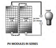
Series wiring connections are made at the positive end of one module to the negative
end of another module. When loads or power sources are connected in series, the voltage
increases. Series wiring does not increase the amperage produced. The image at right shows
two modules wired in series resulting in 24 V and 3 A.
Series circuits can also be illustrated with flashlight batteries. Flashlight batteries are often
connected in series to increase the voltage and power a higher voltage lamp than one battery
only could power alone.
Question:
When four 1.5 VDC batteries are connected in series, what is the resulting voltage?
Answer: 6 volts
2. Parallel Circuits
Parallel wiring connections are made from the positive to positive terminals and
negative to negative terminals between modules. When loads or sources are wired in
parallel, currents are additive and voltage is equal through all parts of the circuit. To increase
the amperage of a system, the voltage sources must be wired in parallel. The image at right
shows PV modules wired in parallel to get a 12 V, 6-amp system. Notice that parallel wiring
increases the current produced and does not increase voltage.
Batteries are also often connected in parallel to increase the total amp-hours, which increases
the storage capacity and prolongs the operating time.
3. Series and Parallel Circuits
Systems may use a mix of series and parallel wiring to obtain required voltages and amperages.
The image at right shows four 3-amp, 12 VDC modules wired in series and parallel. Strings
of two modules are wired in series, increasing the voltage to 24 V. Each of these strings is
wired in parallel to the circuit, increasing the amperage to 6 amps. The result is a 6-amp, 24
VDC system.
4. Batteries in Series and Parallel
The advantages of a parallel circuit can be illustrated by observing how long a flashlight will operate before the batteries fully
discharge. To make the flashlight last twice as long, battery storage would have to be doubled.
If a series string of four batteries has been added in parallel to another string of four batteries to increase storage (amp-hours). The
new string of batteries is wired in parallel, which increases the available amp-hours, thereby adding additional storage capacity and
increasing the usage time. The second string could not be added in series because the total voltage would be 12 volts, which is
not compatible with the 6-volt lamp.
5. High Voltage PV Arrays
So far, we have only discussed input voltages up to 24 V nominal. Today, most battery less grid-tied inverters on
the market require a high voltage DC input. This input window is generally in the range of 350 to 550 VDC. Because of the inverter's
high voltage input requirements, PV modules must be wired together in series in order to sufficiently increase the voltage. High
voltage arrays are now possible with Off Grid Systems with the use of an MPPT charge controller. These MPPT charge controllers
can generally take up to 150Voc ( Open circuit voltage) and step down the voltage to the battery bank while increasing the amps to
the battery bank. The advantage of using MPPT charge controllers is clear in the size of the wiring required between the array and
charge controller and in the number of parallel strings required. We have a chart which makes it easy to see the total array size
depending on battery voltage and the maximum open circuit voltage input for each charge controller.

