
SQFlex Solar Pumping Kits can be found here - Grundfos SQFlex Soalar Water Pumping Kit on The Solar Store
INSTALLATION MANUAL
Grundfos SQFlex Solar Water Pumping Kit
INSTALLATION MANUAL
Contents:
| IMPORTANT INFORMATION | |
| BEFORE INSTALLATION | |
| SPLICE CONNECTION INSTALLATION | |
| PUMP INSTALLATION | |
| PRESSURE TANK INSTALLATION | |
| INSTALLATION IN LAKE OR RIVER | |
| GRUNDFOS KIT CONTENTS AND ADDITIONAL ITEMS NEEDED | |
| INSTALLING SOLAR PANEL ARRAY | |
| TOP OF POLE MOUNT | |
| WIRING CONTROLLERS AND PUMP |
Grundfos SQFlex Solar Water Pumping Kit
INSTALLATION MANUAL
IMPORTANT: Read this manual carefully before installing or operating the pump. • Review instructions before operating the pump.
• Electrical installation shall be in accordance with the National Electrical Code, and all applicable local codes & ordinances.
• This submersible pump may be capable of developing very high pressure. A 100 PSI pressure relief valve must be installed between the pump and pressure tank to avoid possible danger of the tank burs.ng that can cause property damage, personal injury, or death.
WARNING - RISK OF ELECTRICAL SHOCK:
• Always disconnect power before servicing.
• Have a qualified electrician provide electrical power to motor.
• Ensure lead and ground wires are properly waterproofed and securely connected. • This pump is built to be used in a water well. Never use it in swimming pools. • Never test a pump or use a pump outside a well without grounding it and submerging in water.
BEFORE INSTALLATION
Inspect your pump and motor for damage prior to installation. The well should be thoroughly developed by pumping out all fine sand and foreign matter that can damage the pump, normally done by the well driller. Your submersible pump must be installed at a minimum of 10 feet (3 m) from the bottom of your well in order to prevent aspiration of sand by the pump. Use only cable specifically designed for well water use. DO NOT USE ROMEX.
SPLICE CONNECTION INSTALLATION
*Splicing connectors are protected by heat-shrink tubing.
1) Remove 3/8” (9.5 mm) insulation from ends of motor leads and drop cable wires. 2) Slide plastic heat shrink tubing over motor leads.
3) Match grounding wire of drop cable to grounding wire of pump leads. On Grundfos pumps the ground wire is green/yellow. Once identified the other two wires are not polarity sensitive.
4) Insert cable and motor wires into butt connectors (Fig. A). Crimp connectors and solder with Rn (Fig. B). Pull leads to check if the connections are secure.
5) Center heat-shrink tubing over butt connectors (Fig. C) and heat with a torch (a match or lighter IS NOT RECOMMENDED).
IMPORTANT: Keep torch moving, because too much concentrated heat may damage tubing. Let tubing cool before moving to prevent cracking.

PUMP INSTALLATION
1) Use a high quality pipe (160 PSI or 200 PSI polyethylene or SCH80 PVC pipe) that will withstand high pressure produced by the system.
2) Cut the pipe at the exact length that you need. Remember that the pump must be installed at a minimum of 10 feet (3 m) from the bottom of the well.
3) All pumps have a check valve installed. For installation over 200 feet (60 m), install an extra check valve at the tank entrance and at each 100 feet (30 m).
4) If using poly pipe use high quality barbed adapters and double stainless steel hose clamps to connect the pump to the polyethylene well pipe.
5) Grundfos SQ Flex pumps have a “Soft start” and a torque arrestor is not required.
6) Fasten the electrical cable to the pipe with wire guides every 25’ or tape every 10 feet (3 m) to avoid damaged wires. At the first fastener above the pump, leave 5” of slack to avoid wire tension. Take care not to scrape the submersible cable against well casing as you lower the pump into the well.
PRESSURE TANK AND CONTROL CENTER INSTALLATION 1) Select a high quality pressure tank that is large enough to allow the pump to run for 1 minute (at minimum) for each cycle.
2) At the connection to the tank, select a tank package that has a check valve, pressure relief valve, hose bib, shut-off valve, pressure gauge, and pressure switch. NOTE: Teflon tape coated with pipe paste is recommended for all threaded brass & stainless steel connections.
3) Never install a water filter or ball valve between the well pump and pressure switch. 4) Do not allow the pump, pipe, or pressure tank containing water to freeze.
ELECTRICAL INSTALLATION
1) It is recommended that a qualified electrician connect the pump. All electrical installations must be in accordance with the NaRonal Electrical Code, and all applicable local codes and ordinances.
2) The Grundfos SQflex pumps do not need a control box to operate. All electrical components are incorporated in the pump/motor. The CU200 and IO101 control boxes provide additional functionality. The Cu200 provides connection for float switch and has digital display. The IO101 provide easy transfer between a DC and an AC power source.
INSTALLATION IN LAKE OR RIVER

Horizontal installation requires the water level electrode to be placed above the pump to ensure the dry-running protection. Shield the pump from direct physical contact. Protect and screen the pump intake to prevent blockage by leaves and weeds. A flow inducer sleeve may be installed over the pump to draw water past the motor for adequate cooling. Protect the entire underwater installation from water currents, ice, etc...

NOTE: A submersible pump is usually isolated at the bottom of a well, where electrical leakage from the motor and cable presents no hazard to human life. This natural protection is lost when installed in a lake, pond or river (there is no way to stop people from entering or touching surrounding water). Take precau.on. TEST WATER QUALITY After installation is complete, sani.ze the en.re well water system. Call your local health department for your local testing procedures.
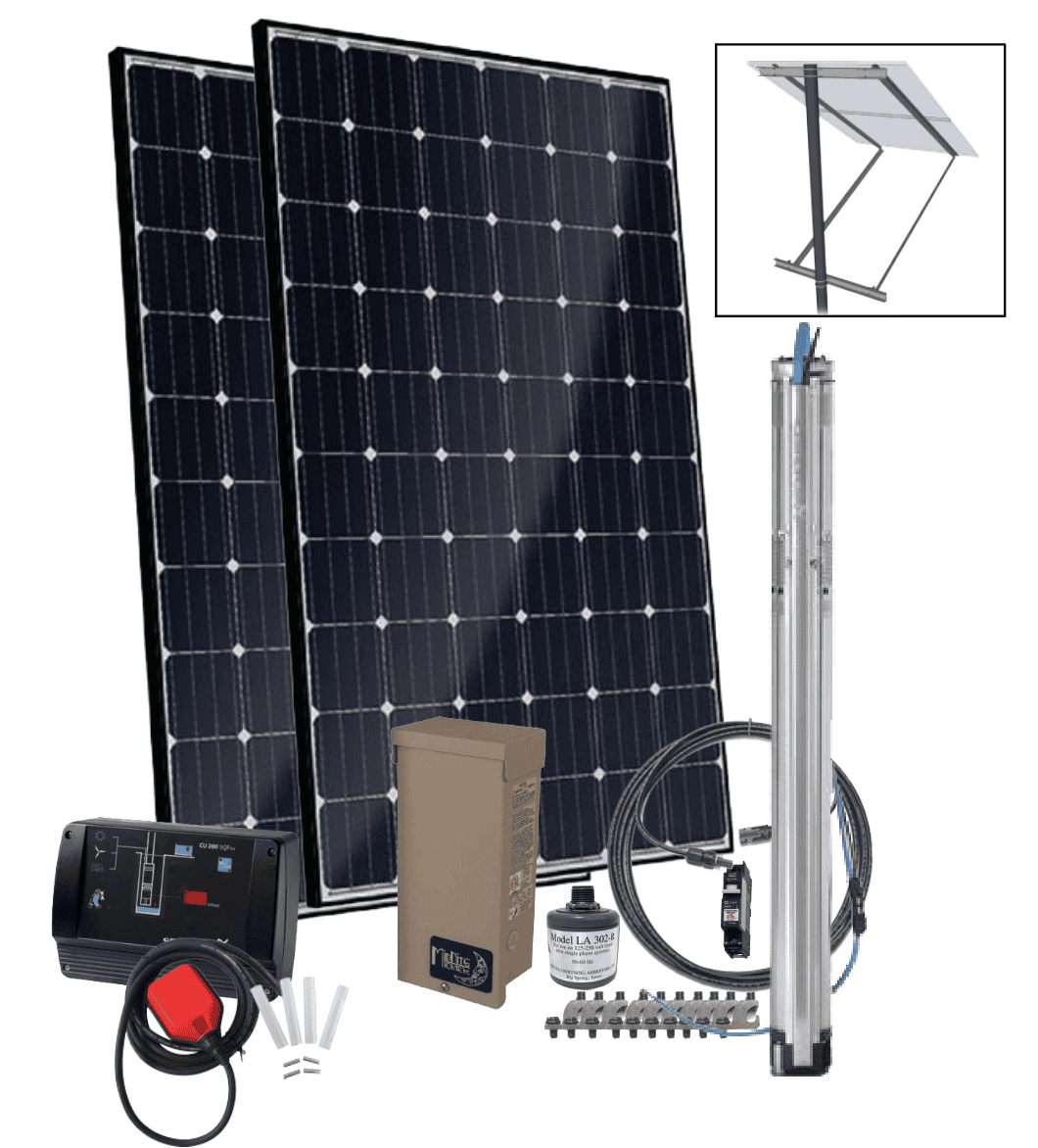
YOUR GRUNDFOS SOLAR WATER PUMPING KIT WILL CONSIST OF THE FOLLOWING PRODUCTS:
Items:
- Mission Solar MS310TS60 310W Module (number dependent on total head and flow rate requirements)
- MC4 Solarline 2 PV Array Output Cable 50' #10 AWG
- Midnite Solar MNPV3 Combiner Box for 3 150VDC or 600VDC breakers
- LA302DC Delta Lightning Arrestor to 0-300VDC - Mounting Bracket Required: No
- Grundfos SQFlex Water Level Switch (use with CU200 only)
- Grundfos SQFlex CU200 Interface Box Pump Controller - Level Switch Required: No
- Grundfos SQFlex ** SQF-* Solar Submersible Pump ( model dependent on total head and flow rate requirements)
- Splice Kit for Submersible Solar Water Pump Wire Grundfos SQF Flex
- Solar Water Pump 5-year extended warranty
- Sun-Rac mounting kit for * panels ( mount size related to number of panels)
- 10/2 with Ground submersible pump cable is NOT included since the placement of the pump in most cases varies. It is available here https://thesolarstore.com/102-w ground-submersible-solar-water pump-cable-p-658.html
The kit will generally arrive in 4 separate shipments usually 5-7 days following order placement. The packages are separated as follows:
-
Solar panels via truck freight (*In order to guarantee replacement of any panels that may have been damaged during shipment, customer must inspect them at the :me of delivery and make an official note of the damage before driver departs)
-
Grundfos Equipment via UPS Ground ( Pump, controllers, warranty, splice, level switch)
-
Solar Panel Mount via UPS Ground
-
MC4 cable, breaker, combiner box, grounding lugs, lightning arrestor via UPS Ground
There are also additional> items to complete the system that are generally available locally and include:
-
6 awg copper stranded wire for grounding solar panels to combiner and then to electrode. • Screws to connect Lugs to solar panel grounding location.
- 8’ Grounding electrode and wire clamp
- Concrete and rebar for the mount hole
- sch 40 steel pipe for mount (Sun-Rac mounts require both vertical and horizontal support pipes)
- Screws to mount combiner box and controller to the pole/mount or Unistrut can be also used for attaching box to poles.
-
Zip Res to attach MC4 extension cables to mount frame.
-
Electrical Conduit to go from solar panels to combiner box and then to below ground
- 10/2 w/ ground UF wire from combiner box to wellhead, you could use same sub pump cable although UF wire is cheaper.
- Drop pipe to pump, diameter dependent on pump model.
- • 3/8 “ Polypropylene Safety rope (not required if using galv steel pipe)
INSTALLING SOLAR PANELS, MOUNTS, MC4 CABLE, COMBINER BOX, BREAKER AND LAY IN LUGS
The Grundfos Predesigned Solar water pumping kit includes Mission Solar MS310TS60 310W Modules which need to be wired in series (positive to negative) for high voltage input to the pump and
or controllers. From the solar panel array we would go to the MNPV3 combiner box using the included MC4 extension cable. The MC4 cable is usually cut in half to allow the MC4 connectors to connect to the solar panels MC4 connectors and allows the bare copper ends to go to the combiner box. The polarity of the wire is indicated on the MC4 cable coming from the solar panel junction box. Do not use the polarity marked on the cut MC4 extension cable. It is a good idea to mark positive with red electrical tape to avoid confusion or use a voltmeter to confirm polarity. Although the pump power lines are not polarity sensitive the connections to the combiner box are. The positive wire will go to the breaker with the negative going to the negative bus bar inside the combiner.
Image below shows 2 panels in series.

|
Diagram (RIGHT) from Midnite Solar MNPV3 instructions. Please refer to manual for additional instructions. http:// www.midnitesolar.com/pdfs/MNPV_Instructions_Rev_A.pdf Diagram shows 3 breakers and 3 series strings of panels. The Grundfos solar water pumping systems only use 1 series string of 2-6 panels. If using more than 6 panels then the solar panels will need to be separated into two strings and therefore 2 breakers to avoid going over the 300vdc max input voltage. The combiner box can be attached to the vertical pole of the mount using metal screws into pilot holes or using Unistrut (preferred optiom). |
 |
Combiner box installed with Unistrut. Image shows 3 breakers.

In the combiner box we would have a 20a DC breaker rated for 150vdc for up to 3 panels or a 20a 300vdc breaker for up to 6 panels in series. For arrays of 8 panels we would suggest two 300vdc breakers in the combiner box. Please note this would require a larger combiner box than the MNPV3 unit.
 |
The combiner box would also house a lightning arrestor. A lightning arrestor is required to validate the Grundfos extended warranty included with the Grundfos Solar Water pumping kits. The Extended warranty extends the warranty period to a total of 5 years. The lightning arrestor is installed in combiner box. The combiner box shows a 300vdc breaker which takes up to 2 spaces. |
TOP OF POLE PANEL MOUNT
The Grundfos solar water pumping kit normally includes a Sun-rac top of pole solar panel mount.
The customer is responsible for purchasing the 4” schedule 40 steel pipe the mount requires for both the vertical and the horizontal structural members. This pipe is normally available locally at fencing suppliers or steel suppliers. Please refer to the installation manual for the Sun-Rac mounts for pipe sizing and hole sizing charts. https://www.manualslib.com/manual/1399484/Spire-4-Technologies-Sun-Rac Srtp-Pm-1.html?page=7#manual
Image shows typical 3 panel Sun-Rac top of pole mounts.
|
The included grounding lugs for the solar panels and mount will be mounted to each solar panel and to the 4” pipe and connect to a customer supplied 6awg bare copper stranded wire to the combiner box and then to a grounding electrode driven near the array into the ground. |
 |
|
WIRING CONTROLLERS AND PUMP The Grundfos CU200 controller provides a combined status and control unit for the SQFlex pump kit system. The CU200 includes a digital display that provides information on the power the pump is using and will display fault codes for troubleshooting the system if needed. AddiRonally, the CU200 enables connection of a level switch placed in a water reservoir or tank. A reverse action pressure switch is used in situations were a float valve is used or if going directly to pressure tank. In most cases this is due to the 2000 feet max distance between the CU200 and the float switch. We have found also that keeping the cu200 and pump within 650 feet is preferred. The optional Grundfos IO101 controller (not included-must be purchased separately) provides easy transfer between the solar array and an AC source such as a generator or grid power. The US version of the IO101 can only take max of 120vac even though Grundfos SQflex pump is good up to 240vac. |
 |
From the combiner box the positive and negative outputs would go to the Grundfos CU200 controller or if you have the optional IO101 controller, it would go to the IO101 first and then the cu200 and then directly to the Grundfos SQflex pump.
Depending on the distance from your solar panels to the wellhead you may want to run underground feeder cable (UF wire) to save money and splice in the submersible pump cable at the wellhead.

Diagram below does not show the combiner box and breaker between the solar array and controllers

The Grundfos SQflex pump has a total of three wires. The yellow and green wire is the ground with the other two wires being non polarity sensitive. The wire is connected to the pump via the included underwater splice kit.
In calculating the flow rates and vertical lift the calculations are based on the static water level rather than the pumps depth in the well. The Grundfos SQFLex pumps have a maximum submergence level of 500 feet from static water level.
Basic overview of installing pump in well:
Procedure:
1. Lay the pump next to the wellhead.
2. Roll out the pipe, rope, and cable side by side, starting from the wellhead. Measure these to make sure you have enough to get to your water level in the well.
3. attach the pipe, rope, and cable to the pump. Use Underwater Cable Splice (included) for the cable connections.
4. Wrap the pipe, rope, and cable together with cable pipe wrap tape heavy duty submersible water well pump vinyl.
5. Create a place to anchor the rope near the wellhead. A sturdy hook on the wellhead or well cap will work.
6. For shallow wells, lower the pump and rope/pipe/cable assembly into the well. This may take two or more people, because it’s heavy. One person at the wellhead, and another person as a safety at the end of the rope. Wear leather gloves so you don’t get rope burn.
7. If you have to lower the pump more than a couple hundred feet, to control the rope, you should use a winch or a sturdy pulley attached to a truck, or attach the rope to a tractor or 4 wheeler. Lay a steel barrel down sideways at the wellhead and run the rope/pipe/cable assembly over it to reduce pinching and abrasion as the rope/pipe/cable goes into the well. You will need more rope on hand with this technique.
8. When the pump is at the correct depth, Re off the rope on the hook or if using a pitless adaptor, secure galvanized drop pipe to assembly.